> For the complete documentation index, see [llms.txt](https://tempdocs.zerog.one/llms.txt). Markdown versions of documentation pages are available by appending `.md` to page URLs; this page is available as [Markdown](https://tempdocs.zerog.one/projects/hydra/build-instruction/phase-1/1.-assembling-left-arm.md).
# 1. Assembling left arm
### Bed supporting arm
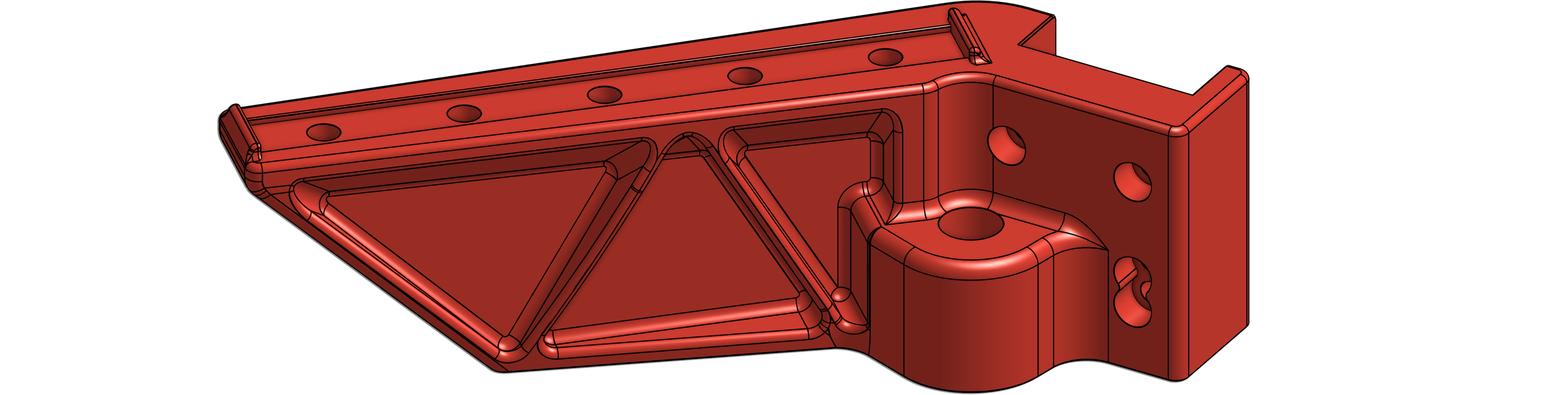
#### Left arm
[](https://docs.zerog.one/manual/build/hydra/left_arm#lightbox__item_1)

The hardware displayed below is for the left arm assembly.
#### **Hardware**
#### **Printed part**
| File Name | Description | Image | Download |
|---|
| left_arm.stl | Front left support arm for print bed
|  | Here |
| MGN9C_12x#Mag.stl |
Connects the bed to the rail carriage |  | Here |

We have very specific [settings](https://docs.zerog.one/standard/print/settings) you should print the parts with, they’ve been designed around these settings.
### Left arm assembly
#### **Inserting the heat inserts**
Printed part required:
| Filename : | left\_arm.stl | [](https://docs.zerog.one/manual/build/hydra/left_arm#lightbox__item_2) |
| ---------- | ------------- | -------------------------------------------------------------------------------------------------------------------------------------------------------------------- |
Hardware required:
| Type:
Amount:
| Heatset insert
9
|  |
| ----------------------- | -------------------------- | --------------------------------------------------------------------------------------- |
#### **Inserting heat inserts for bottom**
Stand your Left arm down on the top surface.
We’re starting our work with the bottom. If possible, clamp it between something, This way, it doesn’t move…
**Don’t burn yourself!** We’re going to work with a soldering iron, be careful. Heatsets inserts are still hot after melting them into the plastic, don’t touch them!
If you do not know how to insert heatset inserts into printed parts, please watch the video by [EDGE OF 3D](https://www.youtube.com/c/EDGEOF3D).
Place the small end of the heatset inserts into the hole. You can start with one heatset so they don’t fall out when you insert the other once. Heat up the soldering iron to about 250℃, you do not want to burn the plastic, you want to let the heatset melt into the plastic. These will be used to mount the leadscrew nut to the arm in a later step.
[](https://docs.zerog.one/manual/build/hydra/left_arm#lightbox__item_4)
> `Not sure if the heatset is in straight? Grab a longer M3 screw, and partially thread it in right after melting it in, this way you can turn it straight.`

#### **Inserting heat inserts for top**
Stand your Left arm down the bottom surface.
Place the small end of the heatset inserts into the holes. And start melting them in as shown in the image below. These will be used to attach the MGN9C rail in a later step.
[](https://docs.zerog.one/manual/build/hydra/left_arm#lightbox__item_5)

#### Installing MGN9 rail
Hardware required:
| Type:
Amount:
| MGN9C 100mm
1
|  |
| ----------------------- | ----------------------- | --------------------------------------------------------------------------- |
| Type:
Amount:
| M3X8mm bolt
5
|  |
Grab the left arm and align the MGN9C rail into the top as shown in the image below.
[](https://docs.zerog.one/manual/build/hydra/left_arm#lightbox__item_6)

Lower the rail into the slot, there are two tabs that’ll keep the MGN9C carriage from riding off the rail. The front tab is shown in the image below.
[](https://docs.zerog.one/manual/build/hydra/left_arm#lightbox__item_7)

#### **Inserting screws into MGN9C rail**
Move the carriage to the back, and thread the first 3 M3x8mm screws into the heatset inserts using a 2.5mm hex driver.
[](https://docs.zerog.one/manual/build/hydra/left_arm#lightbox__item_8)

Now move the carriage to the front and thread the last 2 M3X8mm screws into the heatset.
[](https://docs.zerog.one/manual/build/hydra/left_arm#lightbox__item_9)

#### Mini tank!
Printed part required:
| Filename : | mini\_tank.stl | [](https://docs.zerog.one/manual/build/hydra/left_arm#lightbox__item_3) |
| ---------- | -------------- | ---------------------------------------------------------------------------------------------------------------------------------------------------------- |
Hardware required:
| Type:
Amount:
| Heatset insert
1
|  |
| ----------------------- | -------------------------- | --------------------------------------------------------------------------------------- |
#### **Inserting the heatset insert**
We start by melting the heatset insert in into the so called ‘barrel’, this is the hole in the front as shown in the image below.
[](https://docs.zerog.one/manual/build/hydra/left_arm#lightbox__item_10)

#### Installing Mini tank on carriage
Hardware required:
| Type:
Amount:
| m3x8mm
9
|  |
| ----------------------- | ------------------------------------- | ------------------------------------------------------------------------------------------------------ |
| Type:
Amount:
| Heatset insert
10
|  |
| Type:
Amount:
| 10mm Kossel ball
1
|  |
| Type:
Amount:
| 12x5x4 countersunk magnet
1
|  |
We’ve been working on the left arm and mini tank. It’s time to install the Mini tank onto the carriage. Grab the left arm and mini tank you’ve prepared in the steps above.
#### **Installing magnet assembly**
Grab the left arm and lower the magnet into the middle of the MGN9C carriage as shown below.
[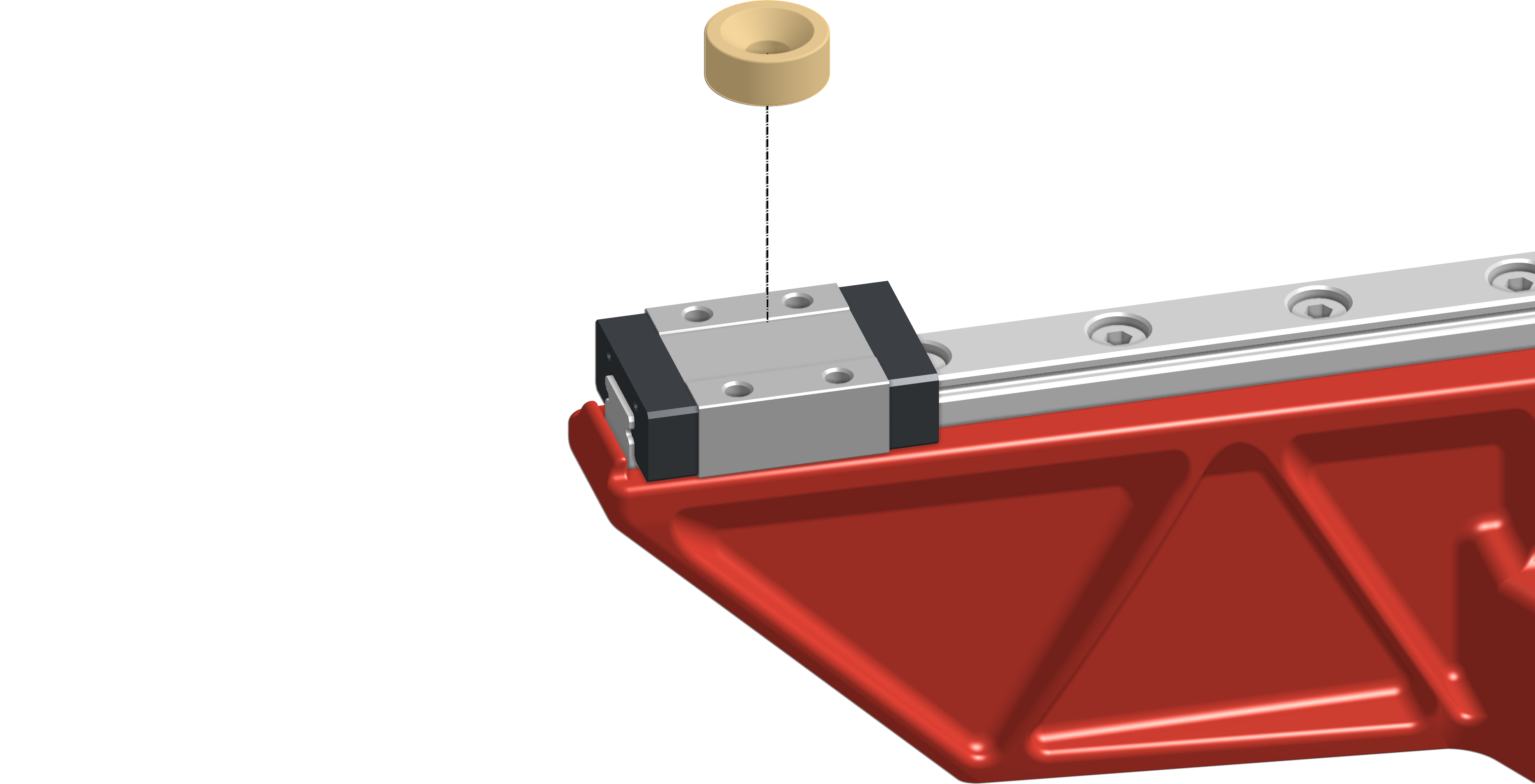](https://docs.zerog.one/manual/build/hydra/left_arm#lightbox__item_11)

Now take the 10mm Kossel ball and center it on the countersunk magnet, note that the threads + hole should face the top.
[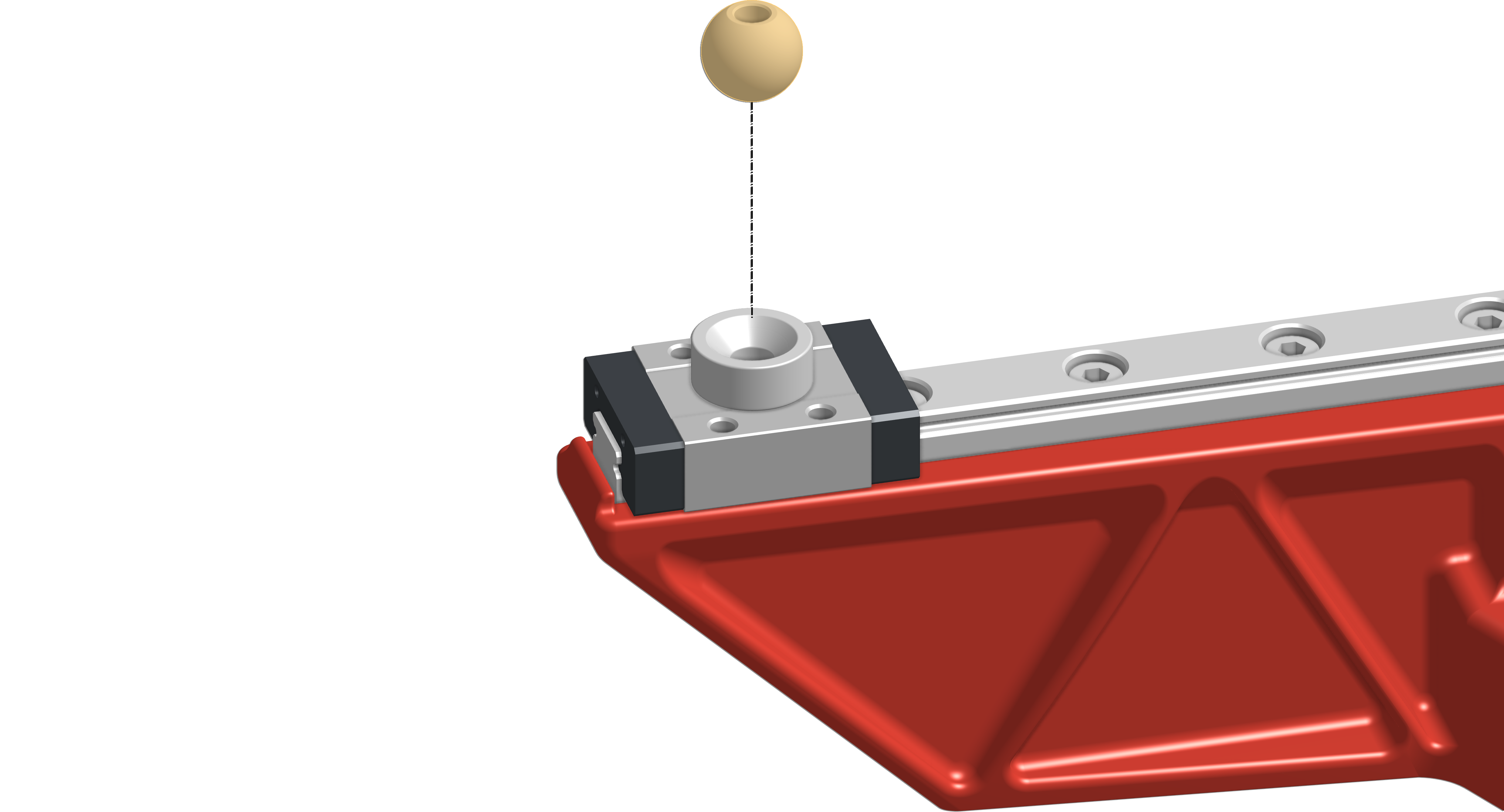](https://docs.zerog.one/manual/build/hydra/left_arm#lightbox__item_12)

Take the Mini tank you’ve prepared, and lower it onto the magnet + Kossel ball.
[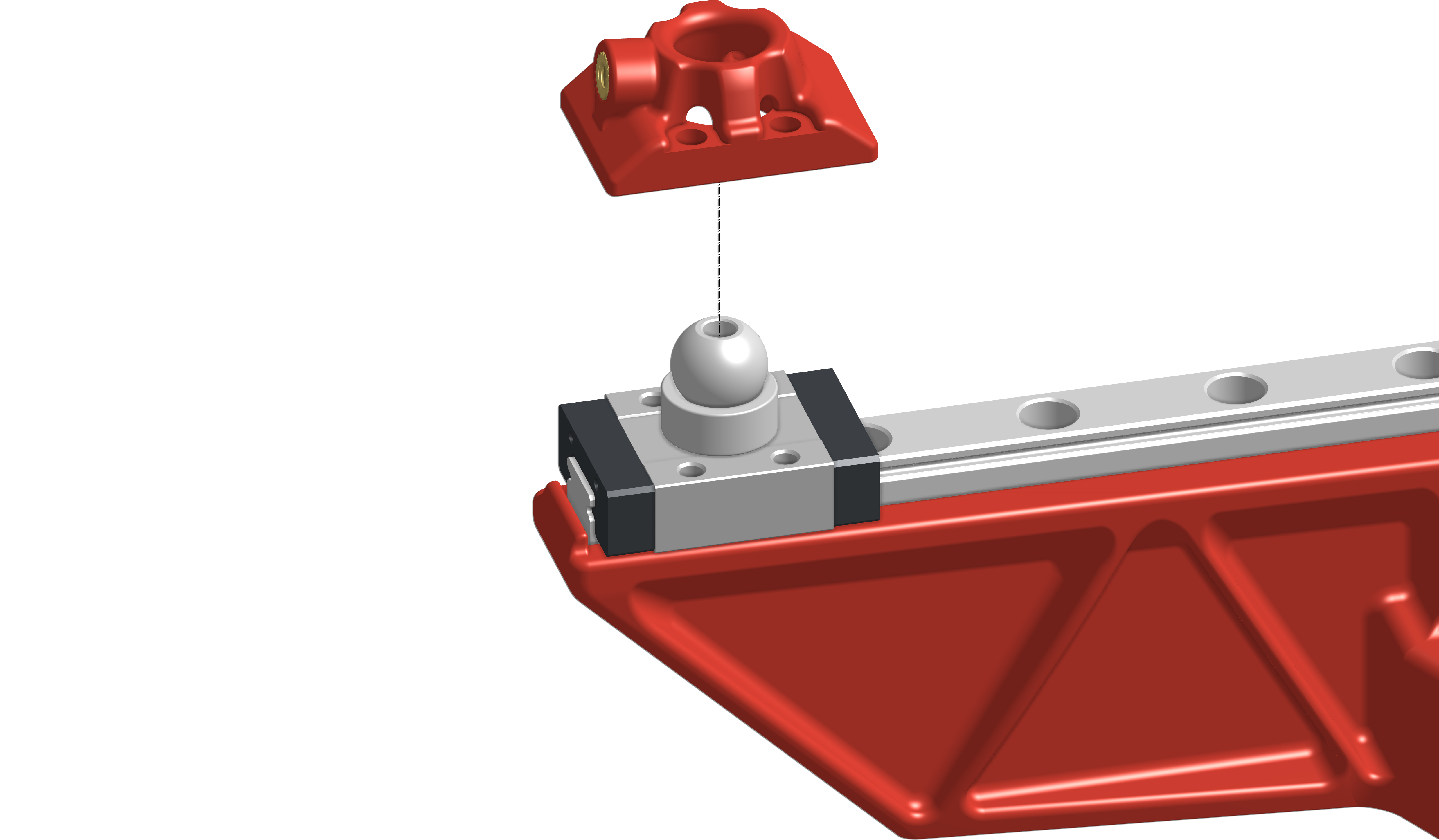](https://docs.zerog.one/manual/build/hydra/left_arm#lightbox__item_13)

Your assembly should look something like this:
[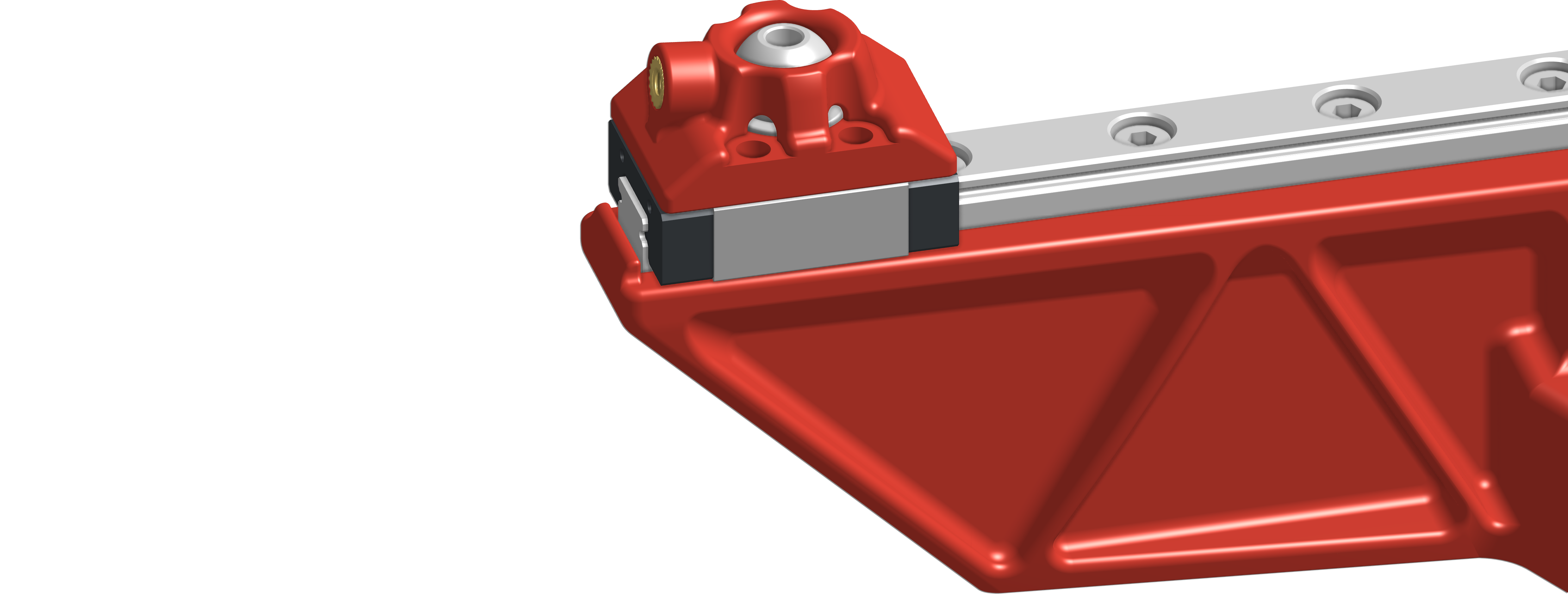](https://docs.zerog.one/manual/build/hydra/left_arm#lightbox__item_14)

#### **Inserting the screws**
Install all 4 M3x8mm screws into the top of the Mini tank and thread them into the MGN9C carriage as shown below.
[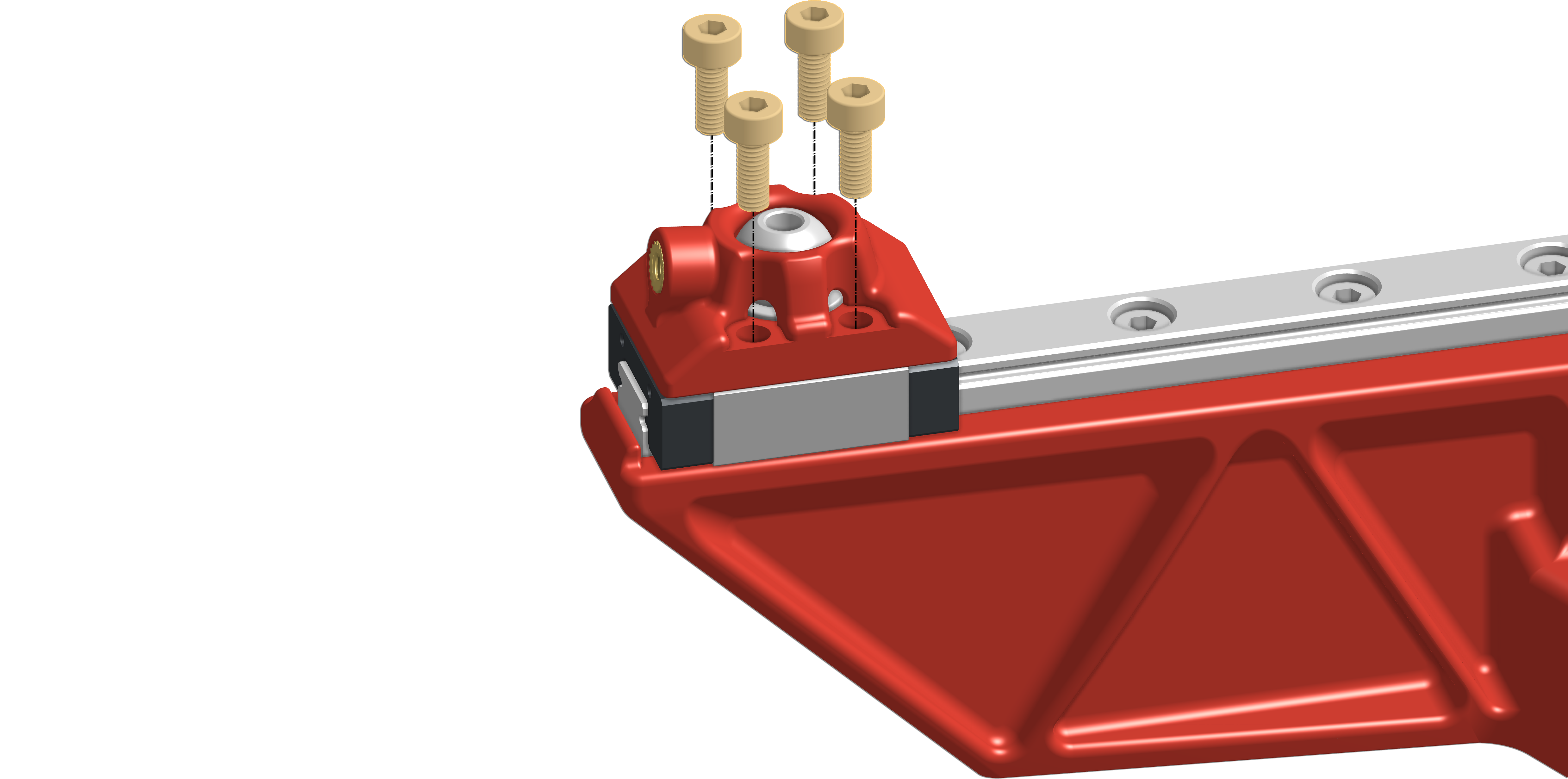](https://docs.zerog.one/manual/build/hydra/left_arm#lightbox__item_15)

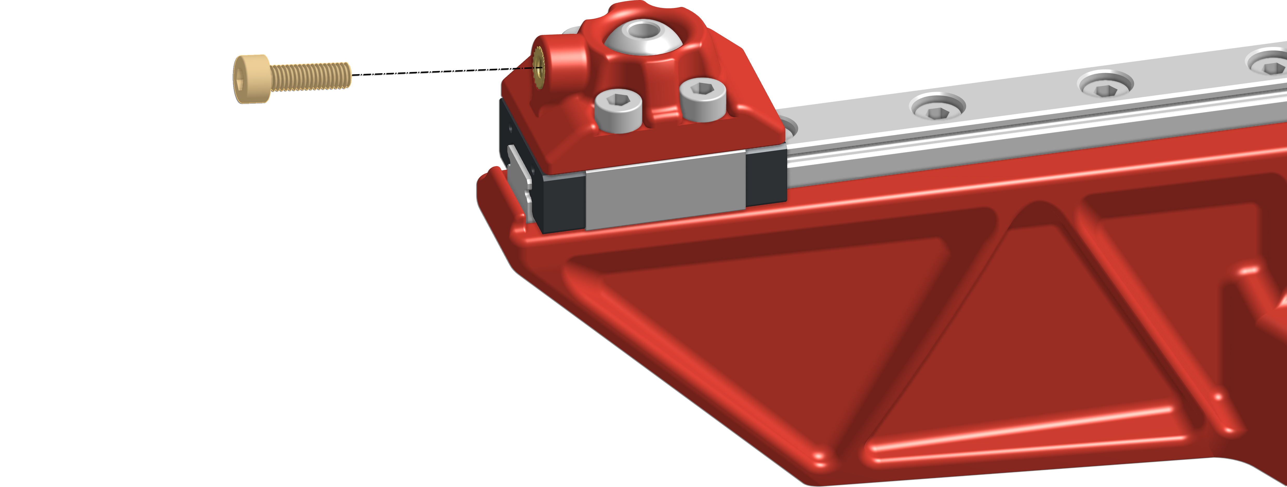
#### **Installing locking system**
This system is used to prevent the kossel ball from spinning when installing and uninstalling the bed. A **light snug fit** should be more than enough.
Hardware required:
| Type:
Amount:
| m3x10mm
1
|  |
| ----------------------- | ------------------- | --------------------------------------------------------------------- |
When you’ve installed everything, you need to make sure the M3x10mm bolts are lose. Locking them into place will stop your Z-system from trimming correctly and might actually damage parts.
Grab the assembly and your M3x10mm screw and lightly thread it into the barrel as shown below. **Light fit is enough!**
[](https://docs.zerog.one/manual/build/hydra/left_arm#lightbox__item_16)

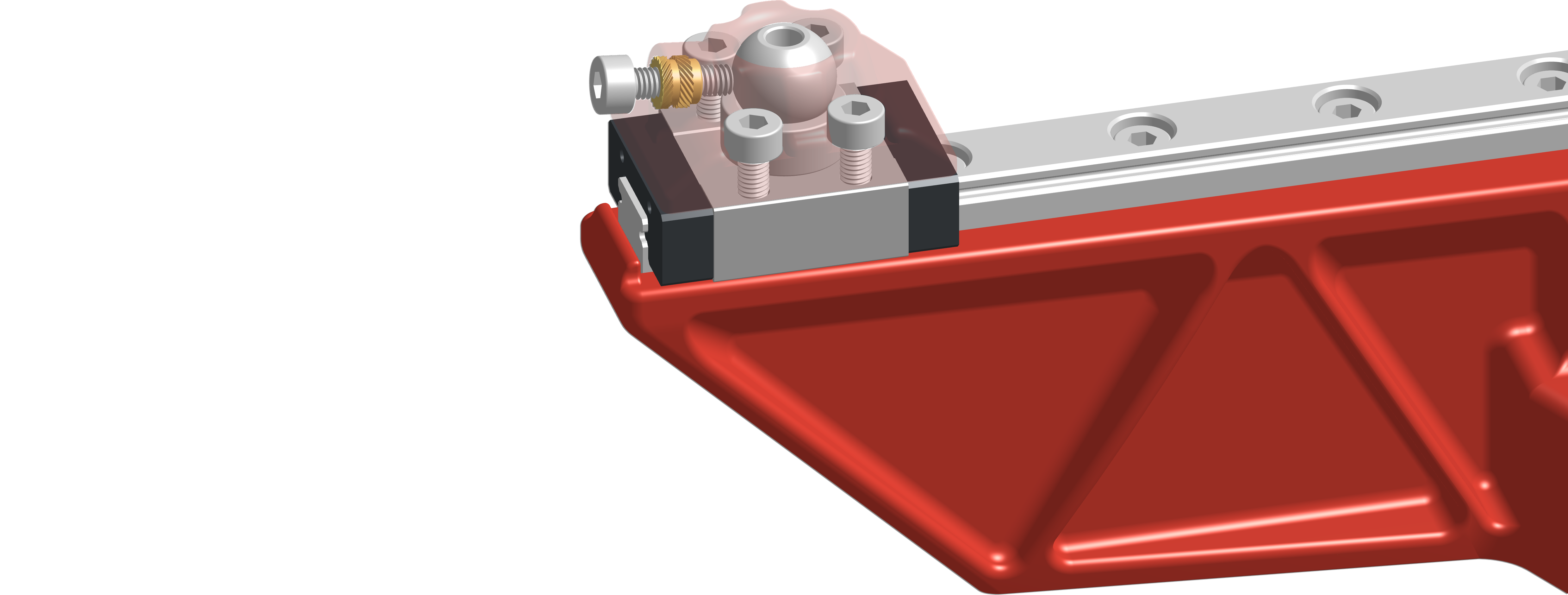
The following image shows you how it will lock the kossel ball into place, hopefully, this will help you understand how it functions.
[](https://docs.zerog.one/manual/build/hydra/left_arm#lightbox__item_17)
---
# Agent Instructions
This documentation is published with GitBook. GitBook is the documentation platform designed so that both humans and AI agents can read, navigate, and reason over technical content effectively. Learn more at gitbook.com.
## Querying This Documentation
If you need additional information that is not directly available in this page, you can query the documentation dynamically by asking a question.
Perform an HTTP GET request on the current page URL with the `ask` query parameter, and the optional `goal` query parameter:
```
GET https://tempdocs.zerog.one/projects/hydra/build-instruction/phase-1/1.-assembling-left-arm.md?ask=&goal=
```
`ask` is the immediate question: it should be specific, self-contained, and written in natural language.
`goal` is optional and describes the broader end goal you are ultimately trying to accomplish on behalf of the user. GitBook uses it to tailor the answer towards what is most useful for that goal.
The response will contain a direct answer to the question and relevant excerpts and sources from the documentation.
Use this mechanism when the answer is not explicitly present in the current page, you need clarification or additional context, or you want to retrieve related documentation sections.

